Difference between revisions of "16 LEDs"
Jump to navigation
Jump to search
| Line 4: | Line 4: | ||
== Overview == |
== Overview == |
||
A very useful board to test your digital outputs. Works on 5V as well as 3.3V so for the DIO as well as the Pi GPIO pins. |
|||
Must have! Use the 10x1Pin F-F kabel to hook it up to the boards. |
|||
== Assembly instructions == |
== Assembly instructions == |
||
Revision as of 16:37, 24 April 2013
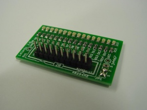
This is the documentation page for the 16-LEDs board.
Overview
A very useful board to test your digital outputs. Works on 5V as well as 3.3V so for the DIO as well as the Pi GPIO pins. Must have! Use the 10x1Pin F-F kabel to hook it up to the boards.
Assembly instructions
No user adjustable settings.
Possible Configurations
External resources
Related projects
| pin | function | ||
|---|---|---|---|
| 1 | 2 | GND | GND |
| 3 | 4 | LED1 | LED2 |
| 5 | 6 | LED3 | LED4 |
| 7 | 8 | LED5 | LED6 |
| 9 | 10 | LED7 | LED8 |
| 11 | 12 | LED9 | LED10 |
| 13 | 14 | LED11 | LED12 |
| 15 | 16 | LED13 | LED14 |
| 17 | 18 | LED15 | LED16 |
| 19 | 20 | VCC | VCC |
Common Ground/Common VCC is hard wired in JP1.
| 1=2 3 | Common GND |
| 1 2=3 | Common VCC |
Jumper settings
Future hardware enhancements
Changelog
2.0
- Initial public release
