Blog 02
Hello,
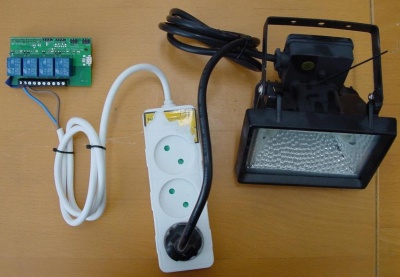
This is my first project with the Raspberry Pi. In this Blog list I will keep you posted about my Raspberry Pi projects. In this project I want to turn on and off a lamp with a Raspberry Relay. After I figured this out, I want to do more useful things with the Raspberry Relay and the lamp.
Before I connect the cables I want to know, where I have to put what were. Or in other words where in the pin-outs do I have to put the cables from the power supply and the lamp itself.
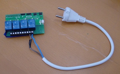
On the wikipedia page from the Relay I found out that the power supply has to be on pin 9 and 10. On pin 10 has to come the (+)blue cable and on pin 9 the (-)brown cable.
To find out where the (+)blue cable and (-)brown cable has to go at the relay. I first checked the relay with a multimeter with give the result same as on the site, that the left side is off and the right side is the relay activated. To know what is left and what is right: On the right side there is a small circle. With this result I know that pin 1( or 3, 5 and 7) is where the (+)blue cable has to be putt in and other pin 2( or 4, 6, 8 ) I have to put the (-)brown cable.
- For getting the (+) and (-) cable I have to cut the cables and remove the rubber shell.
- Check if the cables are really well stuck in the pin-outs. ( By pulling the cables. )
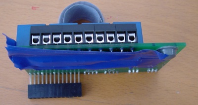
Before putting the Raspberry Relay on the Raspberry Pi: I want to protect the bottom protrusions, with 2 times tape on them so that they don't get trough it. The main reason I do this is because the Raspberry Relay will get 230 volt on it if it will get in contact with the Raspberry Pi, this could give fatal results.
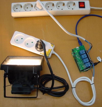
Now I got all the cables connected I want to be sure my power supply is turned off. ( So that I don't get a shock of 230 volt! ) Now I can put it on my Raspberry Pi. When the Raspberry Relay is on the Raspberry Pi you can see a green led on that shows that it is getting power.
Now everything is physical ready ( except the power supply ) we can start the programming.
First I had to download WiringPi, that sees the pins.
Sudo apt-get install git-core
To get the application to download WiringPi.
git clone git://git.drogon.net/wiringPi
To then download WiringPi with the application.
When downloaded I wanted to know if I had all files and all the updates.
cd wiringPi
git pull origin
To make it work type:
./build
First we have to make all the relay outputs. We do that with the code:
gpio mode 0 out
gpio mode 1 out
gpio mode 2 out
gpio mode 3 out
To check if the all the relays work we have to activate them all separate. So every code line has to get it's own turn.
gpio write 0 1
gpio write 1 1
gpio write 2 1
gpio write 3 1
At every line of the code you will hear a loud click sound. All the relays for me worked except the third one. The reason the third relay didn't work was because there was not led + mosfet soldered.
After that I knew which relays worked and didn't. I turned them all off:
gpio write 0 0
gpio write 1 0
gpio write 2 0
gpio write 3 0
When all the relays were off, I could finally turn on the power supply:
gpio write 0 1
and ta da! I burned my eyes!
The End


