Search results
Jump to navigation
Jump to search
Page title matches
- This is the documentation page for the FTDI-serial 2 board. That you can buy in the [http://www.bitwizard.nl/shop/usb-boards/usb The FTDI-serial 2 board has an USB connector and a 4-pin serial/UART connector. The brains of964 bytes (151 words) - 17:53, 6 November 2015
- #REDIRECT [[FTDI serial 2]]27 bytes (3 words) - 11:07, 24 December 2015
- #REDIRECT [[Raspberry Pi User Interface with 16 x 2 LCD with a console serial cable]]85 bytes (13 words) - 13:14, 16 January 2013
- 687 bytes (130 words) - 13:34, 16 January 2013
Page text matches
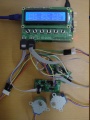
File:27FETsStepperMotorsV.jpg Vertical picture of the 2 Stepper motors being connected with 2 7Fets to a Raspberry Pi.(696 × 928 (78 KB)) - 18:36, 6 November 2015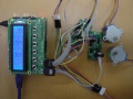
File:27FETsStepperMotors.jpg 2 7FETs connected with the raspberry pi through spi cables. On the 2 7FETs are stepper motors connected.(928 × 696 (79 KB)) - 18:33, 6 November 2015- == Step 2 == [[File:DMX_case_5.jpg|400px|DMX case - step 2]]1 KB (237 words) - 17:02, 31 December 2023
- This is the documentation page for the FTDI-serial 2 board. That you can buy in the [http://www.bitwizard.nl/shop/usb-boards/usb The FTDI-serial 2 board has an USB connector and a 4-pin serial/UART connector. The brains of964 bytes (151 words) - 17:53, 6 November 2015
- #REDIRECT [[FTDI serial 2]]27 bytes (3 words) - 11:06, 24 December 2015
- #REDIRECT [[FTDI serial 2]]27 bytes (3 words) - 11:07, 24 December 2015
- <tr><td>2</td><td>GND</td></tr> 1-2: 3V3<br>1 KB (226 words) - 17:52, 6 November 2015
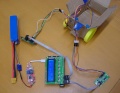
File:StepperCar.jpg The cables outside the box show which cable goes to which object for the 2 wheeled Stepper motor car. Made for [[blog 17]].(843 × 650 (148 KB)) - 16:15, 17 November 2015- <tr><td>2</td><td>GND</td></tr> <tr><td>4</td><td>pin 2</td></tr>4 KB (818 words) - 14:23, 1 February 2012
File:Wiz.png Button 2 = i(1,706 × 1,118 (2.63 MB)) - 11:04, 11 September 2015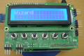
File:Wizard.png Button 2 = i(1,562 × 1,058 (2.24 MB)) - 11:07, 11 September 2015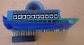
File:Tapeonrelay.jpg In this image you see that the under part of the raspberry relay has 2 times a tape on it, so that it doesn't effect anything it is in contact wit(1,700 × 904 (644 KB)) - 12:00, 11 September 2015- == Working with 2 7FETs Stepper motors == ...ETs( on spi1 ). The other 7FETS also of course has 88 as address. ( On the 2 dots there has to be a hexadecimal number. )4 KB (666 words) - 14:04, 23 November 2015
- | 2 || VCC || power | 1 || 22 KB (309 words) - 10:50, 10 March 2015
- * The only jumper Is for selecting the I/O voltage. 1-2 = 1V8, 2-3 = 3V3.1 KB (210 words) - 17:50, 6 November 2015
- * 2 GND * 2 GND1 KB (167 words) - 11:07, 2 October 2023
- ...t the common-cathode version. This connects all the cathodes to GND (pin 1/2) and then all the inputs to the leds. This results in normal logic: the led To test the 16LED, connect the GND (pin 1 or 2) to any of the GND pins on your board.3 KB (445 words) - 12:59, 11 November 2015
- ...ed 25 through 28. The other pins are numbered 1,3,5,...-23 on one side and 2,4,6,...-24 on the other side. <tr><td>1,2,7,8,10</td><td>GND</td></tr>1 KB (196 words) - 13:05, 11 November 2015
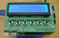
- ...ible that the menu goes up and down and that I then can select between the 2 options displayed on the first and second line of the Rp_ui_board([[User In *2. Select option 26 KB (994 words) - 12:21, 19 November 2015
- | 2 || SDA || Serial I2C Data | 2 || SDA || A4 (Analog input 4) || Digital 20934 bytes (149 words) - 12:12, 10 December 2015


