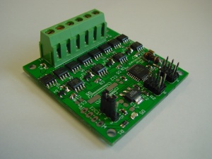
Motor
This is the documentation page for the SPI_motor board. That can be bought in the BitWizard shop.
Contents
Overview
This board is designed to control the direction and speed of two regular (brushed) DC motors, or one stepper motor.
It is of course also possible to (ab)use this board to control other loads, such as pumps, fans, Peltier Elements, lightbulbs, etc.
You can buy this board in our shop
Assembly instructions
None: the board comes fully assembled.
Specifications
Board size: 50mm x 50mm
Maximum motor voltage: 24V
Maximum motor current: 5A or 15A, depending on your version
Possible Configurations
We ship two different versions of this device; a 5A version, and a 15A version.
External resources
Datasheets
Note: Each time we need to order new FETs it turns out the manufacturers have improved and that we can get better fets at a lower price. So... you might have FETs with better specs than these.
Additional software
Related projects
Pinout
For the SPI connector see: SPI_connector_pinout.
The output connector is connected as follows:
(Looking at the business end of the connector, counting from left to right)
| pin | function |
|---|---|
| 1 | Output B1 |
| 2 | Output B2 |
| 3 | Output A1 |
| 4 | Output A2 |
| 5 | GND |
| 6 | Vin |
Jumper
The FET drivers need a 10V to 14V power supply. Please refer to the following table for the correct jumper settings:
| Motor voltage | jumper setting |
|---|---|
| <10V | No jumper, external 10V to 14V power source connected to pin 2 |
| 10V to 14V | Jumper on pins 1 and 2. The motor voltage is used to drive the FETs |
| >14V | Jumper on pins 2 and 3. The onboard regulator generates 12V from the motor voltage. |
If a FET is built to use 12V gate voltages, it will only conduct partially when you drive it with lower voltages. The FET would run hot or self-destruct very quickly if that happens. So to prevent this from happening the FET-driver will not drive the FET at all if the gate-drive-voltage is not above 8V. That is why even if your motor runs on 5V you cannot use 5V for the gate-drive-voltage.
LEDs
The only LED is a power LED.
Jumper settings
See solder jumpers on how to change the solder jumper.
By changing the solder jumper SJ1, you can make connector SPI1 (nearest to the board edge) into the ICSP programming connector for the ATmegaxx8 on the board.
Protocol
For the intro to the SPI and I2C protocols read: SPI versus I2C protocols
The board specific protocol can be found here: Motor protocol
You should also read the General_SPI_protocol notes.
For arduino, a sample PDE is available, called ardemo_lcd.pde, also at BitWizard software download directory .
This is a demo to send things using SPI to the lcd board. The SPI routines there are applicable for the DIO, 3FETS and 7FETS boards as well.
The software
Default operation
Future hardware enhancements
Future software enhancements
TODO: write a library to make handling this board easy.
Changelog
1.0
- Initial public release

